Boldport Club project 5: The Tap
I have long had the wish to learn more about hardware and DIY electronics but never really found the right motivator or opportunity, that is until now. It was the day following “brexit” I saw a tweet retweeted by Travis Goodspeed promoting the Boldport Club (with a 20% discount). The Boldport Club is kind of like an old school book club which sent you a monthly book, only they send you a monthly DIY electronics kit to assemble. I thought this would be the perfect way to finally get into some hardware so I signed up for three months to try it out. In this post I will guide you through the process of assembling the first project: The Tap.
Boldport Club has been running since earlier this year which meant that by the time I signed up they had reached the fifth project, hence the slightly confusing title. While eagerly waiting for my package to arrive, I figured I would need some equipment to work with. I asked around a little in the Boldport Club Slack, another nice feature of the club. Apart from the actual kits you receive you also get to be a part of a community of helpful and enthusiastic peers of varying skill level. In practice, you are invited to their Slack team. I was suggested to get a soldering iron and a multimeter at a not too cheap price. I ended up buying a “Dibotech” (seems like some no-name brand) soldering station and a Uni-T UT139A Multimeter. After watching Saar’s (the founder of Boldport Club) instruction video of how to really beautiful solders, I also bought a pair of Italeri flush cutters. Originally I think they are intended for plastic model sprues but worked perfectly work cutting component legs as well.
Finally, I got the package on the mail. A nice little box filled with a PCB and some components. The schematics and other info is not provided in the package but is instead available online.

I started out with mounting the resistors and wire jumpers, for which I used the cut off legs of one of the resistors. They were then soldered in place, legs cut of with the flush cutters and the solder joint retouched with the iron, just as described in the previously mentioned video.
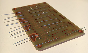
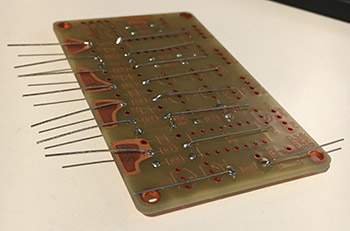
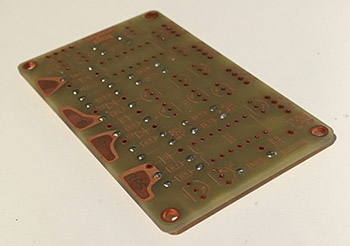
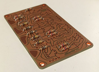
So far, I was really proud of myself since this was basically the first time I had done any serious soldering on my own. The components were in place, the joints looked good, and I even checked the connections with my newly bought multimeter. I finished the remaining “tubular” components by mounting the diodes in the same way as the resistors.
This was feeling like a lot of fun. I continued in the same way with the capacitors. This was probably my first mistake. The reason is that it’s easier to go from lower to higher components when doing the assembly since that makes it much easier to put pressure in the components you are currently adding to keep them in place while soldering. By mounting the capacitors now, it would prove harder to mount the IC DIP sockets later.
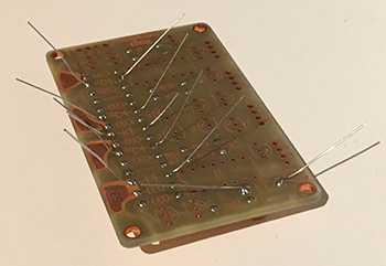
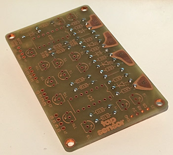
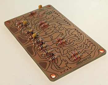
To further set me up in a tight spot, I then mounted the transistors. I started placing the single PNP transistor followed by the 13 NPN transistors as per the instructions. They were then soldered, cut and retouched, just like the other components.
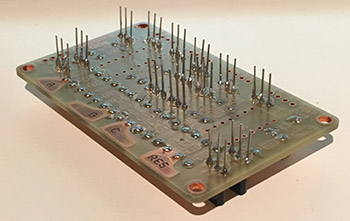
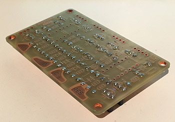
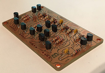
Now, I was almost done, however, thanks to the previous mentioned mistakes, i.e. choosing an unwise order of assembly, I now had some trouble getting the IC DIP sockets to press firmly against the PCB which actually resulted in one of them not lying completely flat on the surface. However, it was connected and the difference is barely noticeable. I finished the soldering by mounting the contacts for the in- and outputs.
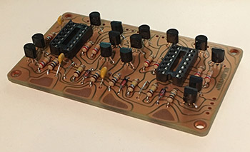
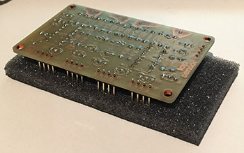
Now, all the components that were to be soldered were in place. Finally, I inserted the NAND gates into the sockets and The Tap was finally done.
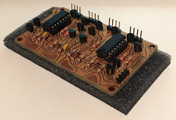
Now, of course, I had to test it somehow so I hooked it up to three LEDs using an Arduino as a 5V source.
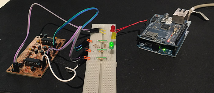
After spending way too much time trying to find a suitable resistor in my box of components, the setup was complete and to my delight, it was working! I don’t think I have been this proud in a long time. I had completed my first real DIY electronics project.
Here is a video of it all in action:
If you found this post inspiring, I urge you to join the Boldport Club as well. As for myself, I’m already looking forward to the next project which should be arriving not too long from now.
