On-Off Keying (ASK) with SDR
About a year ago I bought a HackRF from Great Scott Gadgets with the goal to learn more about radio and in particular software defined radio, SDR. Michael Ossmann of GSG has created a course in SDR which I started following which covers a lot of the basics. After completing the “hello world” of SDR, namely a FM radio receiver and listening to the episode about on-off keying, I started to think about what the next step for me would be. My family have a wireless doorbell which hasn’t been installed yet. It seemed like a perfect candidate for learning more about on-off keying, OOK, or amplitude shift keying, ASK, which it is also called.
In the rest of this post, I will try to keep things general but also talk about what I did specifically with the HackRF. The doorbell consists of two parts, the button which is supposed to be mounted next to the door, and the speaker which is supposed to mounted somewhere inside the house. Building on top of Ossman’s course and a blogpost by Kismet, I started by recording a sample of the button signal.
To record the button I first had to figure out what frequency it was running on. A lot of simple devices like this transmits in the 400MHz area so I opened up a waterfall plot in GNU Radio Companion, GRC, and looked at frequencies in that area. Eventually I found that the button was transmitting at around 433MHz.
To record a sample of the doorbell signal with the HackRF, I used the following command
hackrf_transfer -r Doorbell-430MHz-8M-8bit.iq -f 430000000 -s 8000000This records a sample of 8M samples per second at 430MHz and saved it to a file. The reason we set the frequency to 430MHz, slightly off from the target 433MHz, is to avoid noise caused by the DC offset. I let the program run for a few seconds, then terminated it and opened the file in Baudline. When opening a sample recorded with hackrf_transfer you have to use the following settings in Baudline.
- Sample rate: custom, 8000000
- Channels: 2, check quadrature and flip complex
- Decode format: 8 bit linear (unsigned)
By inspecting the part around 433MHz we get something like this repeated several times.

The bright regions represent signals of high amplitude while the dark areas represent signals of low amplitude. The information is conveyed by changing the amplitude. This is why it is called on-off keying or amplitude shift keying. We can clearly see the long and short bursts of signal. This is very much like morse code where a short burst is a 0 and a long burst is a 1. This particular sample translates to “0011011111110”. We can also note that the signal can be divided into smaller “symbols” where a short burst is the duration of 1 symbol a long burst is 2 symbols long. In between the bursts there is always a one symbol pause. This means that the signal consists of the sequence 0X1 repeated where X is 1 for a long burst and 0 for a short burst.
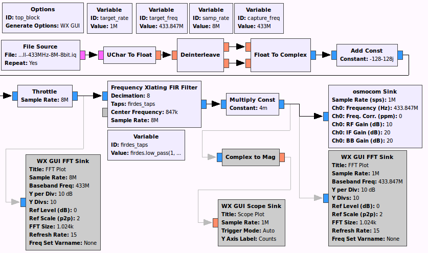
The doorbell can produce 8 different sounds and by trying them all I found out that the first 9 bits are always “001101111” while the last 4 bits determines which sound is used. Now that the signal is understood we want to be able to reproduce it with the HackRF. The first step was to simply replay the recorded sample to trigger the doorbell. I constructed the following flowgraph in GRC based on part 2 of the blogpost by Kismet which reads a recorded sample and transmits it through the HackRF.

Not so surprisingly, this triggered the doorbell. Note that there are some disabled extra blocks for debugging in the flowgraph.
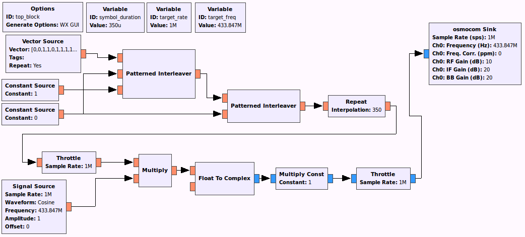
Finally, we want to be able to synthesize the signal from scratch. Since we know that what we want to transmit a sequence of 13 bits there is no need to save the full sample. We can instead create it directly in GRC. This is done with the following flowgraph.

In this flowgraph we put the 13 bit signal in the “Vector Source” block. We use the “Patterned Interleaver” to combine the data source with ones and zeroes to create the 0X1 pattern described above. We then combine this with the zero signal again to repeat the 13 bit signal with a pause in between. Finally we stretch the signal by repeating each bit to make the length of each symbol match that of the recorded signal. We have now created the data signal, all which is left now is to us it to modulate the amplitude of the carrier signal and transmit this with the HackRF. With this I was able to trigger the doorbell. Furthermore, changing to a different sound was as simple as changing the last 4 bits of the data vector.
If you want to play around with the flowgraphs in GRC I have included them in a zip file. In it you will also find a third flowgraph which I used as a oscilloscope to study the signal.
